FLOOR PLAN #
What is Floor Planning?
Floor planning is the Process of placing blocks/macros in the chip/core area, there by determining the routing areas between them.
What Floorplan Determines?
- Size of die.
- Creates wire tracks for placement of standard cells.
- Creates power/ground (PG) connections.
- Determines the i/o pin/pad placement.
How we will decide the good floorplan?
A good floorplan should meet the following constraints.
- Minimize the total chip area
- Make routing phase easy (routable)
- Improve the performance by reducing signal delays
Floor Planning Guide lines:
- Checking of net connection from macro to macro and macro and macro to standard cells. i.e., checking fly lines.and even we can take the reference of data flow diagram.
- Talking macros should be nearer.
- Macros should be placed near the core boundaries.
- More connections of macro to standard cells. Spread macros inside the core area.
- Avoid Criss cross placement of macros in order to save routing resources as well as from routing, placement and congestion issues.
- Spacing is required between macros to avoid congestion around macros
- Leave a halo of space between macros on all sides.
- We should add an appropriate blockage. Either Soft, Partial or Hard blockages as per requirement.
- Create core to die blockages where i/o ports are not placed.
Core Utilization:
- Utilization: Utilization defines the area occupied by standard cell, macros and blockages. In general, 70 to 80% of utilization is fixed because more number of inverters and buffers will be added during the process of CTS (Clock Tree Synthesis) in order to maintain minimum skew.
- Core utilization = (standard cell area+ macro cells area)/ total core area
A core utilization of 0.8 means that 80% of the area is available for placement of cells, whereas 20% is left free for routing.
Macro to Macro minimum Channel Spacing :
Distance between macros can be known from
= ( number of pins of macros * pitch *2) / number of available routing layers
or
Generally space between macros are calculated distance = ( number of pins * pitch ) / (total number of available metals/2)
why we are dividing with 2 means … vertical and horizontal metals so we are dividing.
For example:
We have 2 macros having the pins of 100 each macro and pitch=025 and available metals are 6.
then space between 2 macros = ( ( 100+100)*0.25/(6/2) This distance you should provide between macros.
Inputs for Floorplanning:
Synthesized Netlist .v
Design Constraints (SDC)
Lib files (Physical & Logical)
Technology File
UPF (for low power design)
Sanity checks :
Design checks:
Check if current design is consistent or not.It checks the quality of netlist and identifies:
- Floating pins
- Multidriven nets
- Undriven input ports
- Unconstrained pins
ICC command: check_design:
Checks for multi driven nets, floating nets/pins, empty modules.
Pins mismatch, cells or instances without I/O pins/ports etc.
SDC Checks:
- If any unconstrained paths exist in the design then PNR tool will not optimize that path, so these checks are used to report unconstrained paths
- Checks whether the clock is reaching to all the clock pin of the flip-flop.
- Check if multiple clock are driving same registers
- Check unconstrained endpoints
- Port missing input/output delay.
- No clock reaching to the flipflop clk pin
ICC command: check_timing
Library checks:
• It validate the library i.e. it checks the consistency between logical and physical libraries.
• It checks the qualities of both libraries.
ICC Command: check_library
Physical only cells:
These cells are not present in the design netlist. if the name of a cell is not present in the current design, it will consider as physical only cells. they do not appear on timing paths reports.they are typically invented for finishing the chip.

End cap Cells: End cap cells are placed on both ends of the horizontal site rows and also placed on top & bottom edges (nwell, DRC requirements). When these cells are placed on boundaries of a partition/sub design,we are ensuring that the integration at higher level will not see any abutment problems.
How to insert and at what design phase ?
If you are using IC Compiler : Explore “add_end_cap” command
The best phase is to insert end cap cells right after the floorplan is decided (as part of pre place cells).
Well tap cells: Well tap cells (or Tap cells) are used to prevent the latch-up issue in the CMOS design. Well tap cells connect the nwell to VDD and p-substrate to VSS in order to prevent the latch-up issue. There is no logical function in well tap cell rather than proving a taping to nwell and p-substrate therefore well tap cell is called a physical-only cell. In this article, we will discuss the structure of well tap cell, the requirement of well tap cell and how to place them in the physical design flow.
Well tap cells have no logical functions, it has only two connections.
- nwell to the power supply (VDD)
- p-substrate to the ground (VSS)
- command in ICC: create_tap_cells, specify the name of the library cell to use for tap cell insertion (-lib_cell option) and the maximum distance, in microns, between tap cells (-distance option)
icc2_shell>create_tap_cells -lib_cell myreflib/mytapcell -distance 30
Decap cells: Decap cells are basically a charge storing device made of the capacitors and used to support the instant current requirement in the power delivery network. There are various reasons for the instant large current requirement in the circuit and if there are no adequate measures have taken to handle this requirement, power droop or ground bounce may occur.
These power droop or ground bounce will affect the constant power supply and ultimately the delay of standard cells may get affected. To support the power delivery network from such sudden power requirements, decap cells are inserted throughout the design.
Spare cells: Spare cells generally consist of a group of standard cells mainly inverter, buffer, nand, nor, and, or, exor, mux, flip flops and maybe some specially designed configurable spare cells. Ideally, spare cells do not perform any logical operation in the design and act as a filler cell only.
ICC command:

Filler cells: Filler cells are cells with no logical functionality, but it continues the base layers like NWELL and have the VDD/VSS pins matching the rest of the standard cells.
Innovus command;
setFillerMode -preserveOrder true -core {fill6 fill3 fill1}
addFiller
##To delete the fillers
deleteFiller –cell {fill6 fill3 fill1}
Tie cells: Tie cells are special purpose standard cells whose output is Constant High or Constant Low. These cells are used to hold (tie) the input of other cells which are required to be connected Constant High (Vdd) or Constant Low (Vss) values.
To perform Placement Optimization or Physical optimization, Automatic Insertion and Optimization of Tie offs are required in the design
CREATING A FLOORPLAN
The floor plan describes the size of the core; the shape and placement of standard cell rows and routing channels; standard cell placement constraints; and the placement of peripheral I/O, power, ground, corner, and filler pad cells.
Supported types of floorplans:
Channeled floorplan
Abutted floorplan
Narrow channeled floorplan.
READING THE VERILOG NETLIST:
- Initially, create the library to contain the design by using the following command:
icc2_shell> create_lib Cphylay -ref_libs “/proj1/pd/pdk/tsmc28/9T_libs/hvt28/ndm/tcbn28hpcplusbwp40p140hvt_c.ndm /proj1/pd/pdk/tsmc28/9T_libs/lvt28/ndm/tcbn28hpcplusbwp40p140lvt_c.ndm /proj1/pd/pdk/tsmc28/9T_libs/svt28/ndm/tcbn28hpcplusbwp40p140_c.ndm” -technology /proj1/pd/pdk/tsmc28/9T_libs/tech/tsmcn28_9lm4X2Y2RUTRDL.tf
(or)
icc2_shell> open_lib
- Read the Verilog netlist with the read_verilog_outline command.
icc2_shell> read_verilog_outline {/proj1/pd/users/platha/DC_syn/phylay.vg}
icc2_shell> read_verilog
Reporting Floorplan Information:
- To get the information about the design after initialization, use the following command:
icc2_shell> report_design -all
It’ll gives the following information :
Area
Site row
Blockages
Voltage areas
Power domain
Layers etc
INITIALIZING FLOORPLAN:
- Use the initialize_floorplan command with the appropriate options to create the initial floorplan.
- If needed, refine the floorplan by running the initialize_floorplan command again with different settings for the utilization ratio, side lengths, core-to-boundary spacing, and other settings.
icc2_shell> initialize_floorplan -core_utilization 0.7 -orientation N -core_offset {10.0}

PIN PLACEMENT:
- To place pins, we have to create a pin guide:
icc2_shell> create_pin_guide -boundary {{-0.025 75.075} {0.110 79.200}} -name pg_in [get_ports -filter “direction==in”]
- After creating the pin guide, place the pins by the following command:
icc2_shell> place_pins -ports [get_ports -filter “direction==in”]
(or)
- To place pins automatically, we can use the command:
icc2_shell > place_pins -self
FC_shell:
I have used the following port placement script to place one set of ports
create_bundle -name abc [get_nets -of_objects [get_ports *abc*]]
set_bundle_pin_constraints -bundles qac -allowed_layers {M5 M7 M9 M11} -sides 2 -pin_spacing 1 -keep_pins_together true -range {0.576 1159.44}
set_block_pin_constraints -exclude_sides {1 3 4} -self
place_pins -ports [get_ports *abc*]
MACRO PLACEMENT:
Setting Macro constraints:
- Placement constraints limit the orientations in which macros can be placed.
- Create a collection of macro cells.
icc2_shell> set macro_cells [get_cells physical_context -filter “is_hard_macro && ! is_physical_only” -quiet]
- The following example limits the placement orientation for all hard macros to R0 or R180.
icc2_shell> set_macro_constraints -allowed_orientations {R0 R180} $macro_cells
icc2_shell> set_macro_constraints -align_pins_to_tracks $macro_cells
- Use the report_macro_constraints command to verify the current constraint settings.
Setting Macro Keep outs
- Keep out margins maintain spacing around blocks and macros and help prevent congestion and DRC errors.
- The tool supports four types of keep out margins: hard , soft , hard_macro , and route_blockage.
hard: Prevents standard cells and hard macros from being placed within the keep out margin.
hard_macro : Prevents the placement of hard macros or other hard macro keep out margins within the keep out margin
soft : Prevents standard cells and hard macros from being placed within the keep out margin but at the time of optimization that region can be used.
route_blockage : Prevents the power and ground (PG) router from inserting via arrays that block
access to macro pins. Requires a list of layers to include in the blockage.
icc2_shell> set all_hm [get_cells -hierarchical -filter “is_hard_macro==true”]
icc2_shell> create_keepout_margin -type hard_macro -outer {1.5 2.0 1.5 1.0} $all_hm
icc2_shell> set_app_option -name plan.macro.min_macro_keepout -value 5um
Creating the Initial Macro Placement:
- The below command performs coarse placement on the current design.
icc2_shell> create_placement -floorplan -effort high | medium | low
- Enables congestion-driven placement mode.
- When used with the -floorplan option, you can adjust the behavior of the command with the plan.place.congestion_driven_mode application option.
icc2_shell> set_app_options -name
plan.place.congestion_driven_mode -value both

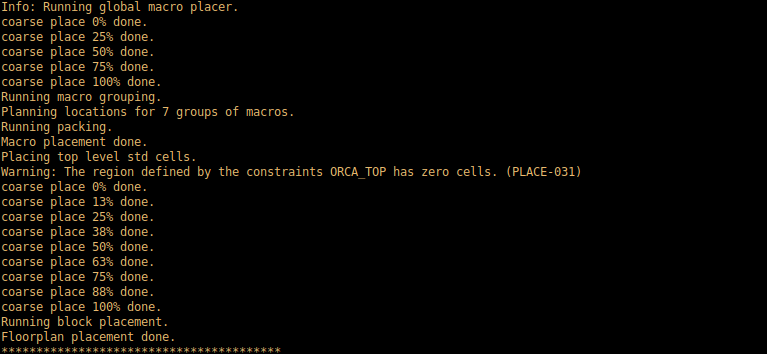
VALIDATING PLACEMENT:
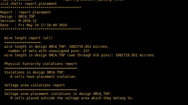
icc2_shell> report_placement -physical_hierarchy_violations all -wirelength all -hard_macro_overlap
- If the design contains overlaps, generate a complete list of overlapping instances with the report_placement command.
icc2_shell> report_placement -verbose high > report.txt
FIXING THE STATUS OF HARD MACROS
- set all_hm [get_cells -physical_context -filter “is_hard_macro &&! is_physical_only” -quiet ]
- set_placement_status fixed $all_hm
- get_attribute -objects $all_hm -name status
TO REMOVE STANDARD CELLS
icc2_shell > reset_placement
What is Congestion?
If the number of routing tracks available for routing in one particular area is less than the required routing tracks then the area said to be congested. There will be a limit for number of nets that can be routed through particular area.
What are the reasons for Congestion
- High Standard cell density in small area
- Placement of standard cells near macros
- High pin density at the edge of macro
- Bad floorplan
- During IO optimization tool does buffering, So lot of cells placed in the core area
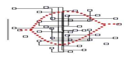
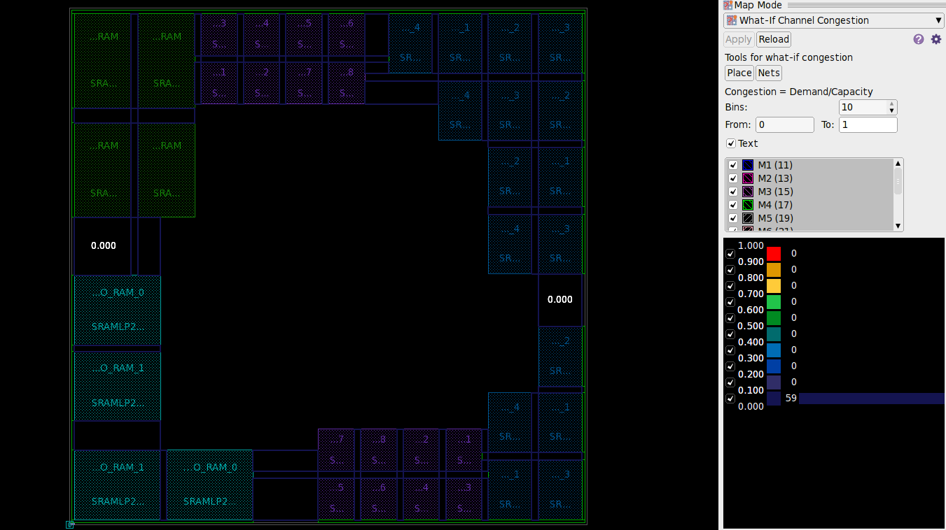
How congestion can be Analyzed?
If the congestion is too severe, the design can be un-routable. This is really not good. It is important to minimize or eliminate the congestion before continuing.
How to fix Congestion?
- Rerun the fast placement with Congestion driven option (Congestion driven placement).
plan.place.congestiondriven_mode -value both
- Modify physical constraints such as adjust cell density in congested areas. Because higher cell density cause for congestion.
- Use/Modify proper blockages. i.e., Soft blockages, Partial blockages, Hard blockages are used proper locations to minimize the congestion near macros.
- Modify floor planing such as moving macros, change core shape/size, Move pins to give enough room for routing.
What happens during congestion driven placement?
As discussed earlier, Congestion driven placement is performed to reduce the congestion. During congestion driven placement, the cells (Higher cell density) which caused for congestion are spread apart. If the cells along timing critical paths are spread apart to minimize congestion, What happens?
If the cells along timing critical paths spread apart, the timing constraints along that particular paths are not met which cause for timing violations. But these violations can be fixed during incremental optimization.
What are the care should be taken using congestion driven option?
- If there is some congestion, use medium effort option
- If the congestion is bad, use high effort option
- If there is no congestion, Don’t use congestion driven option. If we use congestion driven option in this case, It takes more rum time for placement.
How modify physical constraints reduce congestion?
As discussed earlier, Higher cell density can cause for congestion. By default the cell density can be upto 95%. We can reduce the cell density at congested areas by using coordinate option.
As shown in below figure, we can set cell density to a flexible number to reduce the congestion by using the command.
set_congestion_options – max_util 0.6\ – coordinate {x1 y1 x2 y2}
Here we set the maximum cell density upto 60% and given the coordinates for the particular area.

We can use below set app option in innovus, to limit cell density
setPlaceMode -place_global_uniform_density true
setPlaceMode -place -global_max_density 0.6
here 0.6 means 60%. We can give it rom 0.5 to 0.8
How blockages and macro padding(Halos) reduce congestion?
By using blockages and halos, They prevent the tool placing cells in that particular locations to give enough space for routing near the macros.
Soft Blockages allows only buffers/inverters to place. It won’t allow standardcell placement.
Hard blockages always created on the four sides of macro for not to place standard cells and even we can’t place inverters/buffers.
Partial blockages are allowed to blockage or allow the particular percentage of standard cells
- To write the above floorplan information into a file we have to use the command:
icc2_shell> write_floorplan
Which creates a directory contains the floorplan data in the form of .def and .tcl .
- For further use, we can use those files by using the command:icc2_shell> read_floorplan
(or)
In order to get only a .def file, use the command:
icc2_shell> write_def
- For further use, we can use those files by using the command:
icc2_shell> read_def
POWER PLANNING:
- A power grid network is created to distribute power to each part of the design equally.
Flow :
Create and connect power nets ![]()
Create mesh pattern ![]()
Create macro connection pattern ![]()
Create rail patterns
![]()
Set PG strategy
![]()
Instantiate power plan
Create mesh pattern:
- Creating simple pg mesh pattern with metal layers M9 & M8 , with nets VDD and VSS.
icc2_shell> create_pg_mesh_pattern pg_mesh -parameters {w8 w9 fset p s8 s9} -layers {{{vertical_layer: M8}{width: @w8}{spacing: @s8}{pitch: @p} {offset: @fset}} {{horizontal_layer: M9}{width: @w9}{spacing: @s9}{pitch: @p}{offset: @fset}}}
icc2_shell> set_pg_strategy s_pg_mesh -pattern { {pattern: pg_mesh}{nets: VDD VSS}{parameters: 0.8 0.8 0 4.5 1 1}} -core
icc2_shell> compile_pg -strategies s_pg_mesh
Create rail patterns :
- Creating standard cell pattern with metal layer M1
icc2_shell> create_pg_std_cell_conn_pattern sroute -layers M1 -rail_width 0.2
icc2_Shell> set_pg_strategy sroute_pg -core -pattern {{pattern: sroute} {nets: VSS VDD}}
icc2_shell> compile_pg -strategies sroute_pg
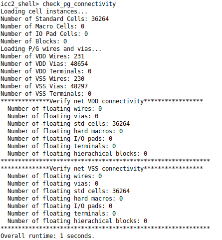
- Checks after PG :
icc2_shell> check_pg_drc
icc2_shell> check_pg_connectivity
icc2_shell> check_pg_missing_vias

CHALLENGES I HAVE FACED DURING FLOORPLAN:
In my recent project, there were 198 instantiations of sub hierarchies and 2.5 million instances along with 32 hard macros.
- Floorplan was a major challenge because of timing and congestion.
- Done multiple iterations of floor plan to fix timing and congestion issues after placement
- Design was not going through route stage as there is a high congestion and huge timing violations.
FIXES I HAVE DONE:
- At first, I have gone through the data low diagram and made the changes in floorplan as per that and I make the better floorplan as I can. After this iteration the congestion and timing improved by some extent.
- Then I have applied the 50% partial blockages where there is a high cell density around the sub hierarchies and macros. After this Iteration, I have seen very less congestion than older run its ~0.1% both directions and earlier it was 25 to 40% earlier. And now the design was converged till route after this iteration.
- And then my focus was mainly on timing and I have seen the main reason for timing violation was the logic sit far away from its hierarchies. So, I have created the move bounds to fix this issue. I was able to fix the timing from 300ps to 100ps violation after this iteration.
For example,
fc-shell> create_bound -name move_bound0 -boundary {{937.8240 769.6000} {1139.6160 838.5520}} -type hard [get_cells hierarchy_name* ]


